Finalizing the Fuel Tank
 After enduring an extensive amount of trials on the fuel tank, it looked like it was finally getting closer to a tank that could be used to hold fuel. As mentioned previously, I had to find the most aggressive solution possible to tackle the remains of the old liner as well as, now, the new liner that I had rolled in. I purchased the MEK in a gallon and put that through the tank in about 5 or so washes. This broke down the stuff inside just as I needed it to. In the end, it didn't get everything so there was a little bit of the old liner left in the seams (this would be coated by the new liner). In any case, it was prepped and I just had to let it sit so that it was bone dry and ready for the new (new) liner.
 |
| Red-Kote Fuel Tank Liner |
At this point, the liner needed to be rolled on every side for about 30 seconds to collect excess, then drain. After going through this process for 40+ minutes, it appeared that no more was really draining meaning that there wasn't much in terms of pooling in the tank (which is what you want). At this point it was left to sit until dry.
 |
| 1975 CB750F Fuel Tank Opening with Red-Kote Applied |
 |
| 1975 CB750F Fuel Tank |

You also might note that the tank is looking pretty rough at this state. After all of the electrolysis, air blowing, chemicals, etc. it has taken a visual toll. In any case it will be eventually be painted so for the time being, it's going to look ugly.
Front Brake
While the tank was drying, I decided to look into another issue. When I first got the bike, there was no front brake lever and the rear brake seemed to have been blown; in other words, the bike had no brakes. I installed the front brake lever almost as soon as I got the bike home. The first time I grabbed the lever it stopped the bike. The problem was that it didn't let go. I ended up having to loosen the caliper to get the bike to move again.I took the wheel off and removed the caliper. As I did, the pads looked fine (not a real surprise) but the piston still wouldn't retract. I pumped the brake a few times and the piston came out slowly. Upon its extraction, I saw the issue at hand. With all parts removed, I could see that water had somehow got into the caliper. As a result, the brake pad, caliper, and piston all had rust and/or corrosion.
 |
| 1975 CB750F Front Brake Caliper (Corroded/Rusted) |
 |
| 1975 CB750F Front Brake Caliper Piston Removed |
I decided that I had to order new pads and an o-ring. I put the piston and caliper into the ultrasonic cleaner (that thing is sure nice to have) to clean the components off. Once I get the new parts, I will reassemble and it should work good as new.
Electrical
Crappy handlebars and controls
Back to the common theme of old bikes, electrical issues. This particular year of bike had controls that were very annoying for a couple of reasons.
 |
| 1975 CB750F Left-Hand Switch |
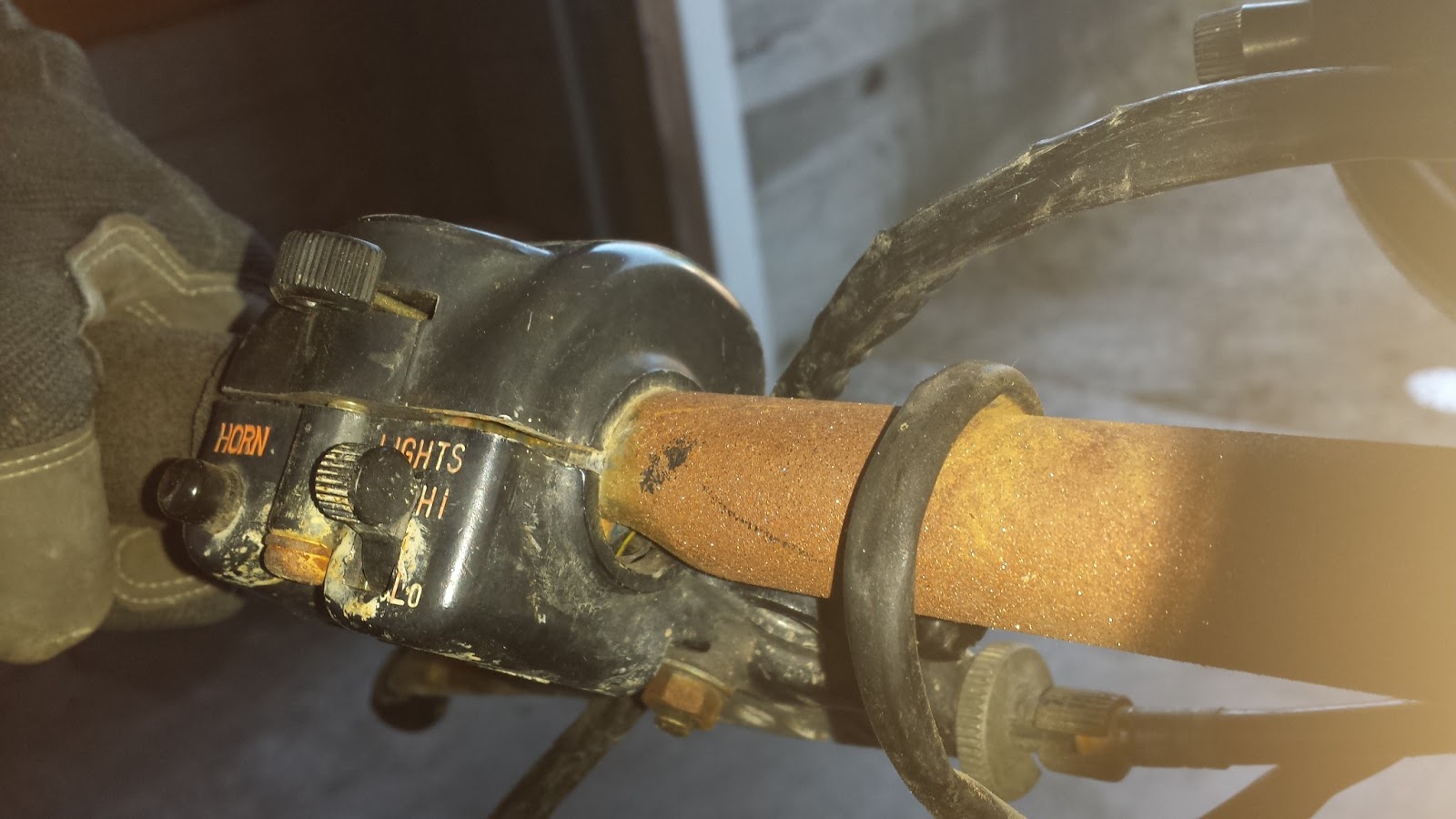 The second issue that the the electrical wiring for the switches has no "out" when mounted on handlebars. This means that the wires have to be run through a hole in the handlebars. This causes a few issues. One issue is that it's very challenging to cram all the wires through one hole and run down the bars and out another cramped hole in the center. Because of this it can cause tears in the wiring insulation. This also means that you're limited to only a few styles of handlebars because there aren't a lot that have holes built in.
 |
| Handlebars for 1975 CB750F |
The Electrical System
 |
| Battery in 1975 CB750F |
The main fuse had blown. In addition, all of the fuses were extremely rusted and the placement within the panel was not correct. I quickly made a new friend: the wiring diagram.
 |
| 1975 CB750F Wiring Diagram |
At this point I had to track down what had caused the blown fuse, whether it was 1 or 100 different things. The first step was to get the fuse box properly organized.
 |
| 1975 CB750F Fuse Box |
If I was going to track electrical issues I had the option of replacing fuse after fuse but I really was looking for a better solution. I kept thinking to myself, why can't there be breakers on automobiles just like houses? I went to the auto parts store to get more fuses and look at my options. Upon looking, I found something magnificent: a 15A breaker! I was stoked. I asked the guy at the store what it was for/how it worked and he had not clue. The best part was that it said automatic reset so I new it was what I was looking for.

I removed the main fuse and wired the 15A breaker in place on the main fuse terminals. Now when I turned the bike on, it did its thing but I was able to keep it on or turn it off and back on and keep working.
There was an array of areas to inspect. Back in the day, there wasn't a lot of use of multiple wire connectors. As a result, there were a lot of one-wire connections.
 |
| 1975 CB750F Stock Wiring for Left Switch |
 |
| 1975 CB750F Wiring within Headlight Assembly |
I decided to start with the left-hand switch because I had the blinker firing. I had no headlight so that was another issue to track. The blinker seemed to work but then tweak out in either left or right position. I wasn't sure if this was an ignition switch issues, an issue with the passage from the main fuse, the head fuse, or the tail fuse, the rectifier, regulator, or what.
 |
| 1975 CB750F Gauges Removed |
I got out my volt meter and started testing in combination with the wiring diagram to see where the current was running and if it was doing what the wiring diagram said it should. I focused on the main components first. Is there power crossing the main fuse? Is the power going through the rectifier? Is the power getting to the ignition switch at the proper voltage? This meant I had to start exposing the terminals to test them so I had to take the gauges and ignition off.
 |
| 1975 CB750F Ignition |
Once I validated that the ignition had the proper voltage, was it providing the proper voltage for the head fuse? Was that traveling properly across the fuse?
After a bunch of testing, I determined that the issue must be the left control. I disconnected the control and toggled the ignition and found that my issues were gone. I then plugged it in piece by piece to see if it would trip the breaker and eventually it did. I now knew that something was shorting in the left-hand switch. I dismantled the switch and reveled that the wires running through the bars were in pretty bad shape. There were too many areas that could have caused the short to make repairing the wires worth while so I knew I needed a new switch.
In the midst of testing the switch itself, I also ran through some testing as to why I had no headlight. I tracked the power source as to what serves what function in the switch and determined that the blinkers were powered through the "winker relay" which gives them pulsed power but the headlight had to have an alternate, constant power wire. I eventually tracked that to be the Black/Yellow wire. Tracing the Bk/Y wire back to the fuse panel, I did some more testing. The power seemed to be getting across the fuse but not from the fuse to the end of the wire that feeds the headlight. I did some more testing and determined that the fuse end quality, as well as the terminals, were in too poor of a condition to properly conduct the current. I cleaned all of the terminals with a wire brush and a light amount of WD-40 and replaced the 7A fuse. This got me the power I needed for the headlight at the end of the wire. I setup a direct connection to the headlight, bypassing the handlebar switch, and it finally worked. Issue, resolved.
Replacing the Switch
Getting a new switch wasn't a big deal because I knew that I wanted to update the switches for more reliable electrical as well as the ability to have different bars (or clip-ons if I decide in the future). I went to a bike junk yard parts type place that we have locally (Luckily. These are not very common.) and started looking for a nice switch from Honda (to hopefully retain a close wiring configuration) that was from a newer bike. In ended up getting one that was off of a 2004 VTR1000F (RC51). The wires were pretty close but not identical. Being that I had a new switch, I had to get a new clutch perch and lever too because the whole old unit was being removed. I ended up finding one that worked from a 1987 CB900C. |
| 2004 RC51 Left Hand Switch and 1987 CB900C Clutch Lever and Perch |
In any case, the mounting point for the horn contact was bent in pretty far and was letting the button push in too far and bind in the housing. I straightened the mount but then there was another issue. The contact point was held in place by very small, non-metallic rings so it wouldn't complete the circuit to actuate the horn. One of this rings to hold the contact in place was broken and no longer functional leaving the contact floating and not secure. This had to be replaced, otherwise the horn would be loose and potentially bind again. Not only did I have to have something small but it couldn't be metallic, so no metal c-clip or wire. I knew I would have a hell of a time trying to find something like this to purchase. This is where I got creative.

I started looking around my garage to see what I could come up with; I needed a thick piece of plastic. I eventually spotted thick plastic in the form of the casing for staple gun staples. I clipped the corner off of the display tab and went to work.
 I cut the size to roughly small enough for the application. I then held the piece in pliers and drilled a hole in the middle, making sure it was big enough to go around the area to retain but not too big to slip past the small flange that would hold it in place. I cleaned up the drilled hole with an exacto knife and then trimmed the edges to size it down and make it closer to a rounded shape. I then cut a small opening in one side to make the piece function like a clip that would flex and slip over into place but stay secured in place once there. After that, I sized it up and it was too thick so I rubbed the piece on sand paper until thin enough and finally had my retaining clip.
(In the first picture, the piece with the orange disk around it is connected to a wire and needs to go through the hole at the bottom of the image in the bracket, then be retained once in place. The bracket is flipped 180 on the other 2 pictures.)
How did I come up with this? I do not know. I'm hoping that these creative solutions keep coming though!
After fixing the horn, I then reassembled the switch unit and the button worked phenomenally.


Since the switch was fixed, it was time to tackle the wiring. The first thing I did was retrieve the wiring diagram for the RC51 from online.
 |
| 2004 RC51 (VTR1000F) Wiring Diagram |
 |
| 1975 CB750F Rewired to Mate with RC51 Switch |
 |
| RC51 Switch on 1975 CB750F |
My electrical issues were resolved so I finally replaced all of the fuses with new ones.
 |
| 1975 CB750F Cleaned Up Fuse Panel |
Ready to fire?
Somewhere in all this I had tested the 4 cylinders for spark and it was good across the board so that was a relief. I had also tested the starter and it turned over just fine. I now had the electrical mostly sorted, and the tank was coated, dry, and ready to be installed so it seemed like I was ready to try and start the bike.
I hooked up the tank, started to fill it with fuel, and it seemed good so I switched the petcock to run/on to fill the float bowls. After a few seconds I had 2 leaks: one on the #3 carburetor float bowl drain plug and one at the petcock. I drained all the fuel out of the tank and all of the float bowls. I then disassembled the petcock to see what the issues was. It appears that I needed a new rubber fuel filter seal, not in the petcock, and a new float bowl drain seal.
I will need to order the parts and can't try to fire until I get the leaks fixed. Time to wait.
In addition, the bike is stuck in 1st gear and I'm not sure why. This may be an issue with a shift fork in the transmission which, if that is the case, will mean that I have to take the engine out and go through it much sooner that I would have liked to. Being that it's on a center stand, I can still fire it up and I'm hoping that if I get the rear wheel spinning that I can pop it out of first but only time will tell.


